GePS - Gesture-based Performance System
USING A DATA GLOVE AS MUSICAL INSTRUMENT
How to build a unit
TOC
- 01 Preparation
- 02 Solder the headers to the Arduino Mini
- 03 Load the code to the arduino
- 04 Connect the MPU6050 sensor
- 05 Test the unit via USB
- 06 Setup XBees
- 07 Connect XBee
- 08 Attach plug for connecting the battery
- 09 Put the LiPo battery into the case
- 10 Sew the unit to the glove
- DONE: Your GePS prototype is ready!
01 Preparation
Get prepared by checking that you have all the required parts ready. Here you can find a shopping list if you need to buy parts.
Parts
- MPU6050 (Triple Axis Accelerometer and Gyro Breakout)
- Arduino Pro Mini atmega328 3.3V 8M, including pin header strips
- FTDI Basic Breakout (USB-TTL 6 PIN 3.3/5V For Arduino, Micro USB)
- Micro USB cable
- Lithium polymer battery (LiPo 850mAh PRT-00341)
- USB LiIon/LiPoly charger (Adafruit Micro Lipo)
- JST Right-Angle Connector (PRT-09749)
- Glove (a thin glove pref. without fingers)
- 2x xBee 1mW Series 1 (WRL-11215, 802.15.4)
- XBee Explorer Dongle (WRL-09819)
- 2mm 10pin XBee Socket - SMD (PRT-10030)
- 3d printed case (you can print it now if you don’t have a case yet)
- Sewing yarn
- Thin insulated cable
Tools
- Soldering iron
- Solder
- Pliers (for electronics)
- Small screwdriver
- Insultation tape
- Marker pen
- Needle for sewing
Software
- GePS PureData package
- PureData extended
- Arduino IDE
- FTDI-Drivers
- I2Cdev Library (from GitHub)
- MPU6050 Library (from GitHub)
- A serial terminal client like minicom, CoolTerm or Putty (more info in Step 06).
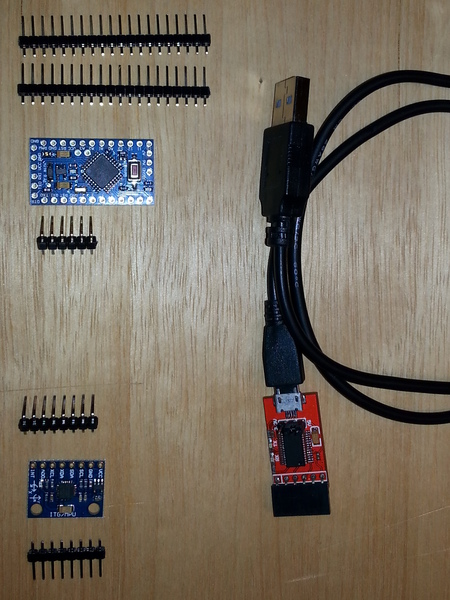
Arduino Pro Mini with pin header strips, MPU6050 sensor and FTDI Basic Breakout with Micro USB cable
Installing the Arduino IDE and FTDI-Drivers
- Download and install the Arduino IDE or use your package manager to install it.
- You will need the FTDI-Drivers in order to communicate with the Arduino Mini.
- For more information read the Arduino Guide.
Arduino Libraries
Get the I2Cdev Library at GitHub
Get the MPU6050 Library at GitHub
Install these libraries into the Arduino Libraries folder inside your home directory. Read this for information on installing libraries.
02 Solder the headers to the Arduino Mini
- Cut a row of 6 pins from the header pin strip that comes with the Arduino Pro Mini.
- Solder it to the Arduino Pro Mini to the sockets GND to DTR.
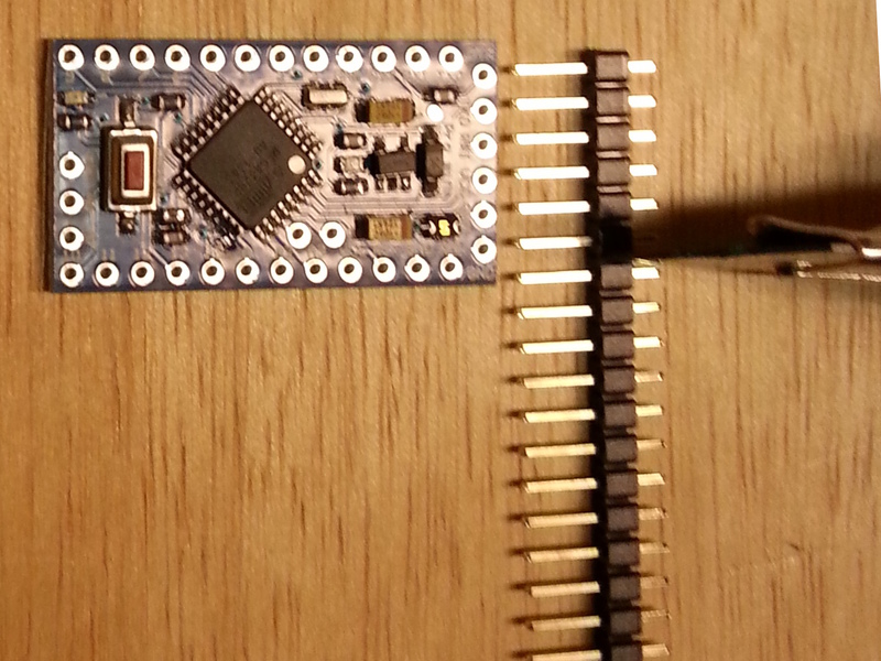
Cutting the 6 headers from the strip
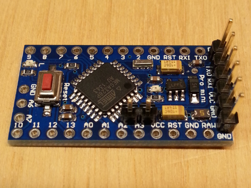
Headers soldered to the Arduino Mini
03 Load the code to the arduino
- Install the I2Cdev and MPU6050 libraries for Arduino
- Download the GePS sketch "main_tx_sensordata.ino" from the GitHub Repository (right-click and save-as...).
- Connect FTDI Breakout to the Arduino Mini, on the headers soldered in Step 02
- Fire up the Arduino IDE
- Select Board: Aruino Pro or Pro Mini (3.3V 8 MHz) w/ ATmega 328
- Select Serial Port: dev/tty.usbserial-xxx
- Select Programmer: AVRISP mkII
- Open the sketch main_tx_sensordata.ino and let Arduino move the sketch inside a folder with the same name if asked.
- Upload the sketch.
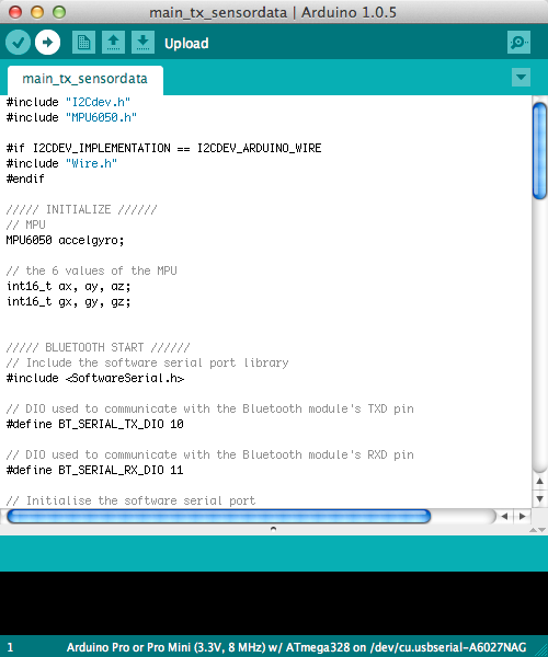
Upload the sketch with Arduino IDE.
04 Connect the MPU6050 sensor
You can disconnect the Arduino from the FTDI breakout for the next steps.
- Cut two pin headers from a remaining header strip
- Trim the long ends of the pins to 5mm
- Solder the shorter ends of the pins to A4 and A5 on the Arduino Mini
The MPU6050 sensor breakout-board will be soldered onto these headers, therefore they have to be soldered tight to the boards.
- Cut two insulated wires at a length of 20mm, remove insulation at the ends (5mm)
- Solder wires to GND and VCC of the Arduino Mini
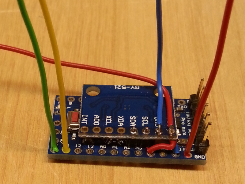
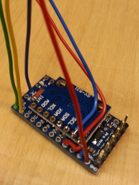
- Place the MPU6050 sensor breakout-board upside down on the Arduino Mini. Solder the other ends of the wires to the sensor at VCC and GND so that the wires cross.
- Solder the sensor breakout-board to the pins sticking out from A4 A5 (Arduino) into SCL and SDA (MPU6050)
Two headers soldered to the Arduino Mini at A4 and A5.

Wires soldered to Arduino Mini at VCC and GND.
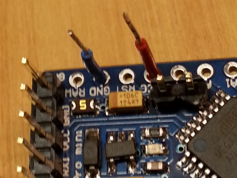
Wires soldered to Arduino Mini at VCC and GND (top view).
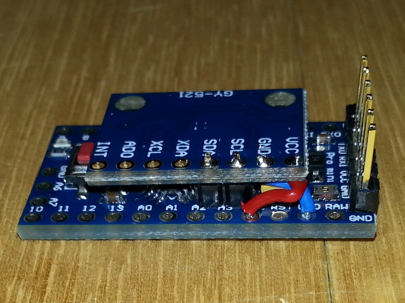
MPU6050 breakout-board soldered to the headers, wires connected.
05 Test the unit via USB
At this stage, the unit is ready to transmit data to the computer.
- Connect the Arduino again, using the FTDI breakout and the Micro USB cable.
- Open PureData (pd-extended) on your computer and load the patch "GePS-MAIN.pd"
- Verify that the serial connection is established in "SERIAL-STATUS"
- View the parsed sensor data by clickling "plot sensor data"
- Move the unit and observe the plots.
If everything workes well, you will see the sensor data plotted, each axis of the accelerometer and gyroscope. If not, verify the following:
- Correct Serial port in the PureData Software?
- Arduino well connected? The red LED should be on
- Test the soldering connections
- Check that the Arduino Sketch is loaded to the board without errors
Close the serial connection and unplug the FTDI breakout from the Arduino.
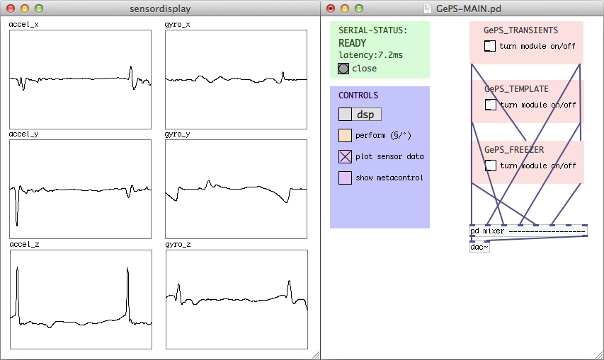
Plotting sensor data in PureData / GePS-MAIN.pd
06 Setup XBees
- Label the XBees with tape and marker pen, one "TX" and the other "RX"
- Plug the "TX" into the dongle and connect it to your computer.
- Setup CoolTerm. Refer to "Setup CoolTerm and open the serial connection" in the right column.
- With the connection open, type the commands as shown in the table "XBee configutation commands" below, using the command parameters for the TX unit.
- Close the connection and unplug the dongle. Swap the TX unit with the RX unit and connect it again.
- Open the connection in CoolTerm and type the commands as shown in the table below, now using the command parameters for the RX unit.
- Close the connection and unplug the dongle. You can leave the RX unit plugged into the dongle, as it will be used like this later on.
XBee configutation commands, step by step
| Command | TX | RX | Comment |
|---|---|---|---|
| +++ | Enter XBee programming mode. Don't press return, but wait until the XBee responds with OK. All follwing commands will be sent by pressing reutrn. | ||
| ATRE | Reset configuration of XBee. | ||
| ATMY | 2 | 1 | Set local ID. |
| ATDL | 1 | 2 | Set ID of unit to connect to. |
| ATID | 1115 | 1115 | PAN ID (Personnel Area Network ID) value can be anything from 0000 to FFFF. Two units communicating with eachother need to have this set to the same value. |
| ATBD | 5 | 5 | Baud rate, this value need to be the same on both XBee modules, so they can talk to each other. You need to choose a baudrate of 38400 once you reestablish the serial connection in order to programm / communicate with the XBee. |
| ATCH | 0E | 0E | Set channel. This can be any HEX value between 00 and 1A. 0E is an example. If you use multiple units (GePS) at the same time, make sure they use different channels. |
| ATWR | Write configuration to XBee memory. |
Refer to the XBee Command Reference Tables if you need detailed information on the AT commands.
The channel ID is superior to the PAN ID, if you use multiple units (GePS), they can use the same PAN ID, but not the same channel ID.
Serial terminal client on your OS of choice
minicom for a Unix-like OS:
$ minicom -D /dev/ttyUSB1 -b 9600
- Ctrl-A A or Meta-A* to add linefeed
- Ctrl-A E or Meta-E* to turn local echo on
- type the AT-commands
- Ctrl-A X or Meta-X* to exit and reset
* In Mac OS X, the Meta-key is "Esc".
For more information / options on Linux/Unix read this article: 5 Linux / Unix Commands For Connecting To The Serial Console .
CoolTerm for any OS:
Setup CoolTerm and open the serial connection
After connecting the XBee with the dongle, open CoolTerm on your computer and set it up as follows (by hitting the Options-button:
- Select the serial-port the XBee is connected on (usbserial-xxx). If the XBee doesn't show up disconnect it, plug it back in and click "Re-Scan Serial Ports".
- Baudrate: 9600 (if you set another baudrate previously, use that one.)
- Data Bits: 8
- Parity: none
- Stop Bits: 1
- Select "Terminal" from the list on the left-hand window. And click "OK"
- Check "Local Echo".
- Click "OK" to save the settings and close the Options window.
- Click at "Connect" icon.
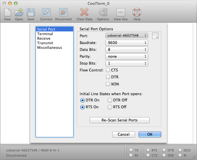
CoolTerm Setup in Mac OS X.
07 Connect XBee
- Prepare insulated wires. Preferably different colors should be used, so you can easily identify the connections. Trim to 100mm and remove the insulation at the ends.
- Solder wires to the Arduino:
- Digital Out 10 and 11
- RAW
- GND (next to A6)
- Solder wires to the MPU6050 breakout-board (bottom facing up):
- VCC (touching the wire connected to VCC of the Arduino)
- GND (touching the wire connected to GND of the Arduino)
- Put the Arduino into the case.
- Bend the wires connected to DIO 10/11 (Arduino), GND (Arduino) and VCC (MPU6050) towards the free space in the case.
-
Prepare the wires in order to be soldered to the headers of the XBee:
- VCC (MPU6050) to VCC
- DIO 10 (Arduino) to DOUT
- DIO 11 (Arduino) to DIN
- GND (Arduino) to GND
- Plug the 10-pin female header to the XBee and solder the wires to it the headers contacts.
Power (red/blue ontop of the MPU) and RX/TX (green/yellow) for the XBEE.
Wires to connect to the LiPo
battery added (red/blue).

Wired Arduino/MPU inside the 3d-printed case.
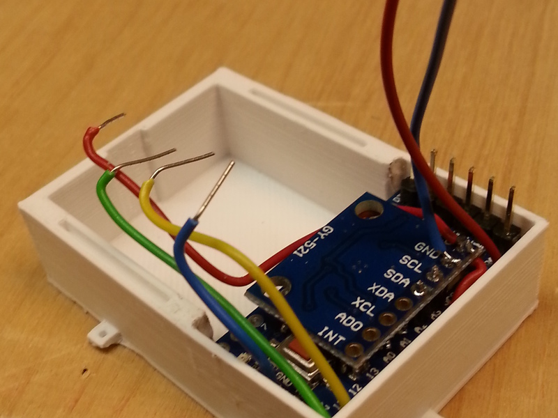
Bending the wires towards the position of the XBee headers.
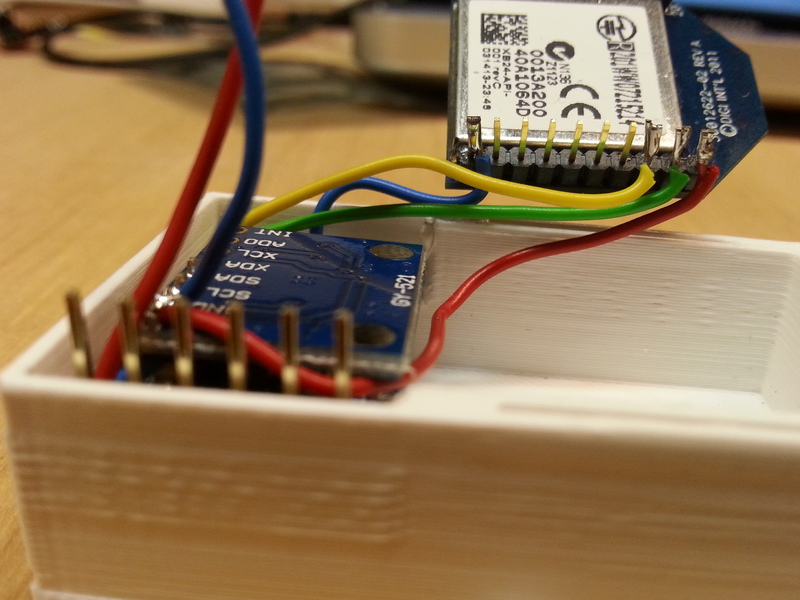
Wires soldered to the XBee headers.
08 Attach plug for connecting the battery
Solder the JST Right-Angle Connector to the remaining wires (to RAW at Arduino and to GND at MPU6050), for connecting the battery.
09 Put the LiPo battery into the case
To avoid damage to the Lithium Polymer battery you should put it into the case only if you're done soldering and cutting parts. The case is designed to have space on the bottom, neatly fitted under the Arduino and Xbee.
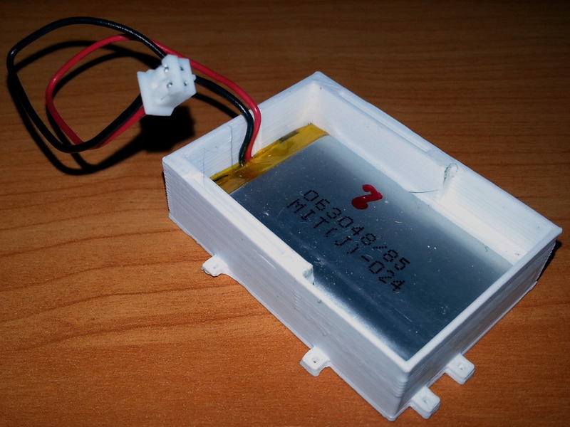
Battery placement
10 Sew the unit to the glove
Place the case with the bottom to the glove, on the palm side towards the wrist. Sew the case to the glove, through the eyelets around the case.
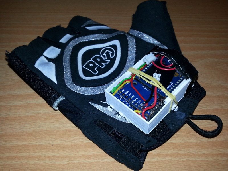
Position and sew the unit to the glove.
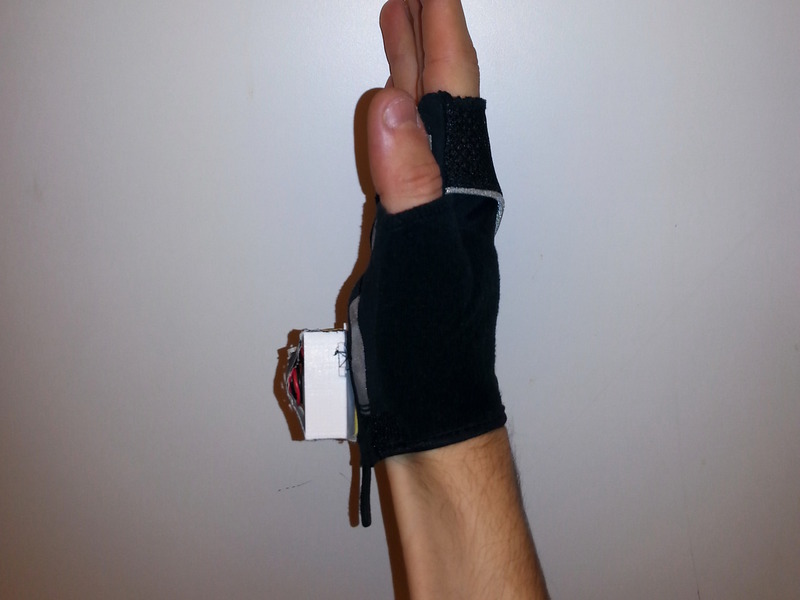
Wearing the glove, the GePS unit sits below the wrist.
DONE Your GePS prototype is ready!
Connect the battery to the JST-plug soldered in Step 08. If everything worked out well, the red LED on the Arduino will turn on. Now you're ready to test the bluetooth connection, you can repeat Step 05, just without connecting the FTDI breakout.
You can cover the unit to keep the parts in place by combining two pieces of insulation tape leaving some space at the ends to stick it to the unit. The second piece of tape keeps the cover from sticking to the parts.
In order to charge the LiPo battery, disconnect the JST connector and connect the battery plug to the LiPo charger, which is plugged into any powered USB port of you computer.